The Airbus A320 aircraft has three independent hydraulic circuits, namely Green, Yellow, and Blue. Each of these circuits delivers a constant hydraulic fluid pressure of 3000 psi (20684271.88 N/m2, 20684.27188 kPa), to power numerous aircraft components. They are all driven independently and have separate reservoirs to ensure redundancy in case of failure of one or two. The hydraulic system is accessed and controlled by the pilot using the overhead Hydraulics Control Panel. It contains pushbuttons for access and control, and fault lights for indication.
Green System
The Green Hydraulic System is pressurized by an Engine Driven Pump (EDP) on Engine No. 1 (portside engine). A fire shut-off valve is located between the system reservoir and EDP. The green system powers the following components:
- Landing Gear
- Slats and Flaps
- Engine No. 1 Thrust Reverser
- Normal Brakes
- Yaw Damper 1
- Rudder
- Stabilizer
- Left Elevator
- Spoilers 1 and 5 (on both left and right side)
- Left and Right Ailerons
- Left and Right Slat Wing-tip Brakes
- Right Flap Wing tip Brakes
Yellow System
The Yellow Hydraulic System is pressurized by an Engine Driven Pump (EDP) on Engine No. 2 (starboard side engine). A fire shut-off valve is located between the system reservoir and EDP. The yellow system powers the following components:
- Flaps
- Nose Wheel Steering
- Alternate Brakes
- Parking Brakes
- Engine No. 2 Thrust Reverser
- Yaw Damper 2
- Rudder
- Stabilizer
- Right Elevator
- Spoilers 2 and 4 (on both the left and right side)
- Left Flap Wing-tip Brake
In case of failure of Eng. No. 2 EDP, the yellow system can be pressurized by a separate electric pump.
Blue System
The Blue Hydraulic System is pressurized by an electric pump. It powers the following components:
- Emergency Generator
- Slats
- Rudder
- Left and Right Flaps Wing-tip Brakes
- Left and Right Slats Wing-tip Brakes
- Left and Right Elevator
- Left and Right Aileron
- Spoiler 3 (both left and right side)
In an emergency, the blue system can be pressurized by the Ram Air Turbine, or RAT. More about it below.
From the above distribution, the rudder is powered by all three systems, making it the most critical component. Other critical components are powered by at least two of the three systems, such as the elevators, ailerons, slats, flaps and stabilizers.
Power Transfer Unit
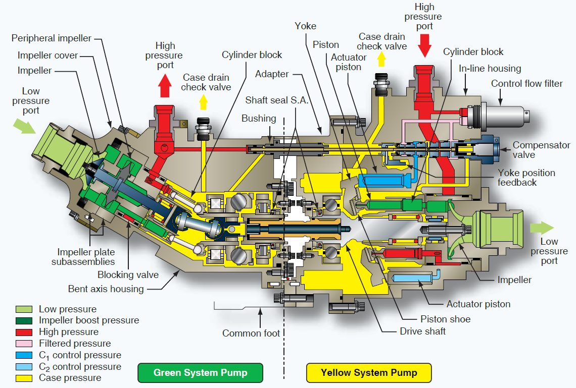
The Power Transfer Unit, PTU, is a component that transfers hydraulic pressure between the green and yellow system in case of a failure of either. It does not transmit hydraulic fluid, lest there be a leak, but rather only the power. In case of a fault such as an overheat, low reservoir volume or low air pressure, it must be switched OFF to prevent it from overheating. It will also not work in the following conditions:
- When PTU Switch is OFF
- When the Parking Brake is ON, and only one ENG MASTER Switch is ON
- When the Parking Brake is ON, Nose Wheel deactivated, and only one ENG MASTER Switch is ON
- When the cargo doors are being operated
The PTU on the A320 is basically a bidirectional, hydromechanical unit that acts as a motor-pump combination. It consists of a bent-axis fixed-displacement motor/pump mated to a straight-axis variable displacement motor/pump by a common drive shaft. When one system faces low hydraulic pressure (such as the Yellow system when only ENG No. 1 is started/running during taxi), the high pressure system runs the motor on its side of the PTU. And since this motor is connected to a pump impeller on the other side (low pressure side) via a common shaft, the hydraulic fluid on the low pressure side will be sucked and forced to run the impeller on its side. This movement will occur in a series of pressure surges, and will only stop once the hydraulic pressure on both sides normalizes. The surges also occur audibly in a loud noise that can be likened to a barking dog. Thus the PTU operates automatically in the event the pressure differential between the Green and Yellow system exceeds 500 psi.
Ram Air Turbine
Ram Air Turbine (RAT) is a small wind-driven turbine stowed in a recessed compartment on the underbelly of an A320 fuselage. It is deployed either automatically or manually in case of total electrical or hydraulic failure in flight, where its blades are spun by the rushing airflow (ram air). This rotation drives an electric generator which provides electric power to critical instruments. The rotation also drives the hydraulic pump connected to the blue hydraulic circuit.
ECAM HYD Page
The hydraulic system on an Airbus A320 is displayed on the HYD page of the ECAM (Electronic Centralized Aircraft Monitor). This page displays the following parameters:
Hydraulic System Status
Displays a green-coloured arrow pointing upward to a white-coloured set of GREEN, BLUE and YELLOW in case of normal operating pressure. When pressure drops on a specific line, the green arrow and white name associated with that circuit turn to amber.
Hydraulic Pressure
Displays the pressure on the three hydraulic lines, in green if normal, and in amber if below 1450 psi. If this data cannot be acquired by the System Data Acquisition Concentrator, SDAC 1, then an amber XX value is displayed.
ENG Pump (Yellow/Green)
It is displayed in green colour if the pumps are running, but amber when they are off. It displays a LO status when the pump is running but the pressure is low.
Fire Valve
When the valve is open, the dispay is green, but when it is closed the display is amber.
Reservoir
The reservoir level is indicated by a movable index, which is usually displayed in green when normal, and amber when below 3.5 litres.
Other parameters displayed include ELEC, OVHT, RAT link, among others.
Components of the Hydraulic System
Reservoir
The reservoir is the tank which stores hydraulic fluid. It usually contains baffles to prevent sloshing. Fluid flows from the reservoir to the pump, where it is forced through the system and eventually returned to the reservoir. The reservoir furnishes a place for the fluid to purge itself of air bubbles that may have entered the system.
Filter
This is a screening or straining device used to clean hydraulic fluid, preventing foreign particles and contaminants from remaining in the system.
Valves
Valves act as control devices in the hydraulic lines.
Filter Bypass Relief Valve
It permits hydraulic fluid to flow in case the filter clogs. Contaminated fluid is better than no fluid at all.
Flow Control Valves
This is a general term for valves which control the speed and/or direction of fluid flow in the hydraulic system. Examples are selector valves, check valves, sequence valves, priority valves, shuttle valves, quick disconnect valves, and hydraulic fuses.
Selector Valve
It controls the direction of movement of a hydraulic actuator. Therefore it allows the simultaneous flow hydraulic fluid both into and out of a hydraulic unit. There are two main types of selector valves: open-center and closed-center. An open-center valve allows a continuous flow of hydraulic fluid through the valve even when the selector is not in a position to actuate a unit. A closed-center valve blocks the flow of fluid through the valve when it is in the NEUTRAL or OFF position.
Check Valve
It allows fluid to flow unimpeded in one direction but prevents or restricts fluid flow in the opposite direction.
Sequence Valve
It controls the sequence of operation between two branches in a circuit i.e. it enables one unit to automatically
set another unit into motion. For example on the A320, it is used in its landing gear actuating system. When the gear selector is set to DOWN, the landing gear doors must open before the landing gear can extend. Conversely, when the selector is set to UP, the landing gear must be completely retracted before the doors close.
Priority Valve
In the event of low hydraulic pressure, the priority valve ensures that critical hydraulic components such as flight control actuators are powered before non-critical components.
Quick Disconnect Valve
Usually installed in hydraulic lines to prevent loss of fluid when units or components are removed.
Relief Valve
It is used to limit the amount of pressure being exerted on a confined liquid. This is necessary to prevent failure of components or rupture of hydraulic lines under excessive pressures. The pressure relief valve is, in effect, a system safety valve, according to the FAA’s Aviation Maintenance Technician Handbook – Airframes, 2023. The most common types of relief valves are ball type, sleeve type and poppet type.
Pressure Reducing Valve
It is used in hydraulic systems where it is necessary to lower the normal system operating pressure by a specified amount. Pressure reducing valves provide a steady pressure into a system that operates at a lower pressure than the supply system.
Shuttle Valve
It is used to isolate the normal system from an alternate or emergency system.
Shutoff Valve
It is used to shut off the flow of fluid to a particular system or component, as and when required by the pilot or system computer.
Accumulator
The accumulator is essentially a steel sphere or cylinder divided into two chambers by a synthetic rubber diaphragm or piston respectively. The upper chamber contains hydraulic fluid at system pressure, while the lower chamber is charged with nitrogen. The accumulator has four main functions:
- To dampen pressure surges in the hydraulic system caused by actuation of a unit.
- To supply extra power to supplement the power pump when several units are operating at once.
- To store power for the limited operation of a hydraulic unit when the pump is not operating.
- To supply fluid under pressure to compensate for small leaks that would cause the system to cycle continuously by action of the pressure switches continually kicking in.
Heat Exchanger
Typically stored in the aircraft’s fuel tank, it aids cool hydraulic fluid, while at the same time raising the temperature of the fuel to prevent potential icing.
Actuator
It transforms the energy in hydraulic fluid into linear motion, to allow operation of units such as pistons.
Seal
It is used to limit movement of undesirable objects. It can prevent fluid from passing a certain point, and keep air and dirt out of the system. There are three main classes of seals; packings, gaskets and wipers.
In conclusion, the A320, being a fully fly-by-wire system, requires a set of computers to monitor its health. It has two System Data Acquisition Concentrators (SDACs), which are identical and interchangeable. These computers will collect data, including hydraulic fluid pressures and reservoir levels, then send their findings to the Flight Warning Computers (FWCs). The FWCs will then cross-check the parameters against predefined logic gates, and if an anomaly is detected, they will generate the corresponding auditory clicks, chimes, and master caution lights. At the same time, the Display Management Computers (DMCs) will pick up the processed visual data strings from the SDAC and draw the schematic representation onto the lower ECAM System Display (SD) on the HYD page.