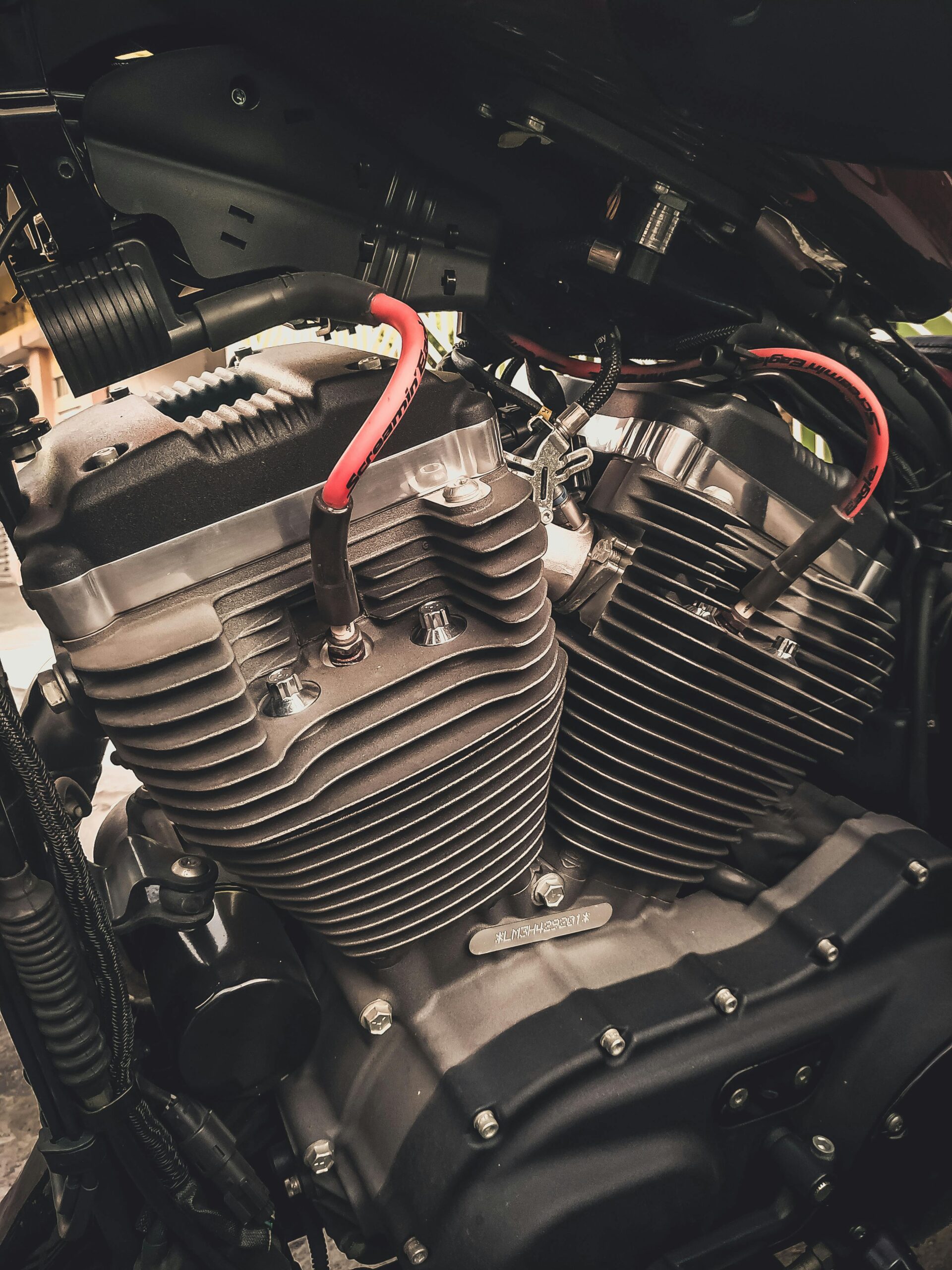
Question! What does Ford, General Motors, Toyota and Honda have in common?
They are all engine builders.
And what does Rotax, Lycoming and Continental have in common?
They are all engine builders.
So what does Ford, Rotax, Lycoming, General Motors, Toyota, Continental and Honda have in common?
They are all reciprocating engine builders!
So what’s a reciprocating engine?
The reciprocating engine, known more commonly as the piston engine, is an internal combustion engine that utilizes the reciprocating motion (up-down movement) of its internal components (called pistons) to run its external components (or load) in a rotary motion.
It is a complete mechanical technological masterpiece – meaning it does not need software to tell it how to run. Only a starting motor and well-oiled components.
But First the History
The reciprocating engine was first experimented and used in the 1700s, and in 1794, an Englishman named Robert Street designed a single-cylinder engine that ran on liquid fuel.
The fuel would be fed into the cylinder, then air pumped manually to raise the piston. Then burning coal would ignite the fuel and the explosion caused on ignition would push the piston up to drive a rocking beam connected to the load. As the piston cooled, it would be lowered by gravity, and pulling the rocking beam.
Years later, in 1860, the first practical gas engine was built by a Frenchman named Jean Joseph Etienne Lenoir. This engine utilized illuminating gas as a fuel, and ignition of this fuel was provided by a battery system.
Then in 1876, Nicolaus Otto, working with Gottlieb Daimler and Wilhelm Maybach, patented a reciprocating engine which utilised four unique piston movements to satisfy rotary movement. These four piston movements are up-down strokes named intake, compression, combustion and exhaust.
Parts of a Reciprocating Engine
A reciprocating engine must incorporate systems that allow fuel to be mixed with atmospheric air, then to be compressed, to be burnt up and finally to be relieved of all exhaust gases.
These systems are accurately called induction systems (for the intake of air), fuel feed systems (for the intake of fuel), ignition systems (for the ignition of the fuel/air mixture), lubrication systems (for the smooth motion of all moving parts of the engine) cooling systems (for the cooling of the hot parts of the engine) and fire protection systems (for detection and extinguishing of unwanted fires in the engine)
But for the engine to run, it must have the following parts:
The Crankcase
This is the foundation of the engine. Usually made of Aluminium alloy (which is both light and strong, it is the housing that encloses the various mechanisms surrounding the crankshaft. It contains the bearings in which the crankshaft revolves. It also provides a tight enclosure for the lubricating oil. It supports various internal and external mechanisms of the power-plant, including providing a base of support for engine cylinders. It provides mountings for attachment to the body as well.
The Crankshaft
It is the backbone of these types of engines – essentially a shaft forged from extremely strong steel alloys such as Chromium-Nickel-Molybdenum Steel, and composed of one or more cranks (also called throws). It transforms the reciprocating motion of the piston and connecting rod to rotary motion for running the engine. The crankshaft is composed of the main journal (the centre of rotation of the crankshaft which keeps the crankshaft in alignment under all normal conditions of operation), the crankpin (which lies off centre from the mail journal, it is the journal for a connecting rod bearing, and is usually hollow to reduce the total weight of the crankshaft, to provide a passage for the lubricating oil. and to serve as a chamber for collecting sludge), the crank cheek (or crank arm, it connects the crankpin to the main journal and is usually drilled through to allow passage of Iubricating oil to the main journal) and counterweights (to provide static balance for n crankshaft) and dampers (to relieve the whip and vibration caused by rotation of the crankshaft). Crankshafts come in four major types: single-throw, double-throw, four-throw, and six-throw.
The Connecting Rod
Made of tough steel alloy (SAE 4340) is the link which transmits forces between the piston and the crankshaft of an engine. It comes in three types: plain, fork-and-blade, and the master-and-articulated type.
The Piston
Made of forged or cast Aluminium alloy, it is a plunger that moves back and forth within an engine cylinder barrel. It transmits the force of the burning and expanding gases in the cylinder through the connecting rod to the engine crankshaft. As the piston moves toward the crankshaft in the cylinder during the intake stroke, it draws in the fuel-air mixture, and as it moves toward the cylinder head, it compresses the charge. Ignition takes place and the expanding gases cause the piston to move toward the crankshaft. On the next stroke (toward the head), the piston forces the burned gases out of the combustion chamber (cylinder). The piston enables rotation of the crankshaft via some structures called plain bearings. A bearing is any surface that supports or is supported by another surface. It is used to enhance minimum friction and maximum wear resistance. A good bearing has two broad characteristics: it must be made of a material that is strong enough to withstand the pressure imposed on it and yet permit the other surface to move with a minimum of wear and friction, and its parts must be held in position within very close tolerances to provide quiet and efficient operation and at the same time permit freedom of motion.
The Cylinder
The cylinder of an internal-combustion engine converts the chemical heat energy of the fuel to mechanical energy and transmits it through pistons and connecting rods to the rotating crankshaft. It also dissipates a substantial portion of the heat produced by the combustion of the fuel, houses the piston and connecting-rod assembly, supports the valves and a portion or the valve-actuating mechanism, and supports the spark plugs. The cylinder assembly includes the following components: the cylinder barrel with an integral skirt, cylinder head, valve guides, valve rocker-arm supports, valve seats, spark plug bushings, and cooling fins. The main power section of the engine will comprise of the cylinder assemblies plus the piston, connecting rods and crankcase section to which they are attached, but the two major units of the cylinder assembly are the barrel and the head.
The Valves
The main purpose of valves in an internal combustion engine is to open and close ports, which are openings into the combustion chamber of the engine. One is called the intake port, and its function is to allow the fuel-air charge toenter the cylinder. The other is called the exhaust port because it provides an opening through which burned gases are expelled from the cylinder.
In Conclusion
The major difference between a vehicle engine and an aircraft engine lies in its intended output. A vehicles crankshaft is connected to a gearbox and its motion is transmitted to axles and wheels while an aircraft crankshaft, while also connected to a gearbox, its output is transmitted to a propeller for thrust purposes.
While it may seem like old school technology today, the reciprocating engine has been monumental in providing thrust for thousands of machines on the ground and in the air; hence the saying – it goes up, and comes down, just like the piston.